ASRock 939SLI32-eSATA2: ULi Dual x16 SLI
by Gary Key on March 2, 2006 12:15 PM EST- Posted in
- Motherboards
ASRock 939SLI32-eSATA2: Features
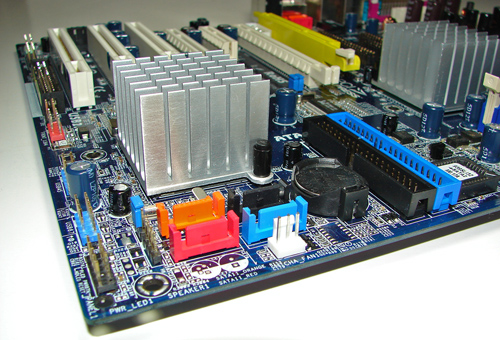
The system fan header is located below the ULi SATA ports. The ULi SATA ports are conveniently located below the M1697 chipset and to the left of the battery. The SATA ports feature the new "clamp and latch" design along with it being color-coded. The ULi M1697 chipset is passively cooled with a high rise heat sink that did not interfere with cards installed into the PCI slots. The TI TSB43AB22 IEEE 1394 chipset is located above the M1697 chipset.
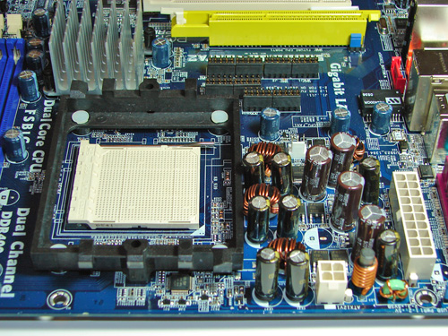
The first physical PCI Express x16 connector is located next to the 12V power connector that must be used if two video cards are installed. The PCI Express x4 and second PCI Express x16 connectors are located next and followed by the (3) PCI slots.
We did not have any issues installing our EVGA 7800GTX 512MB or ATI X1900XTX video cards in the first and second x16 PCI Express slots. These dual slot configuration cards will physically render the PCI Express x4 and first 32-bit PCI slot useless. We did not have any issues utilizing these slots with video cards containing single slot cooling systems.
The ULI M1695 chipset is passively cooled with a large heat sink unit that did not interfere with any installed peripherals. However, this unit did not keep the M1695 chipset cooled properly. We typically witnessed temperatures hovering near 59c from this heat sink, although we did not notice any stability issues during load operations. We do believe additional cooling in this area is required.
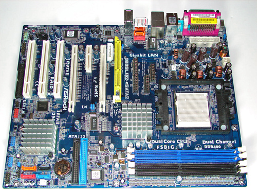
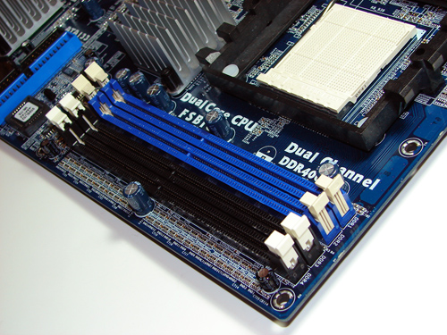
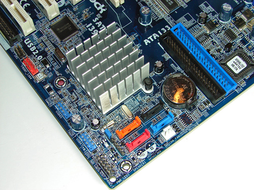
The system fan header is located below the ULi SATA ports. The ULi SATA ports are conveniently located below the M1697 chipset and to the left of the battery. The SATA ports feature the new "clamp and latch" design along with it being color-coded. The ULi M1697 chipset is passively cooled with a high rise heat sink that did not interfere with cards installed into the PCI slots. The TI TSB43AB22 IEEE 1394 chipset is located above the M1697 chipset.
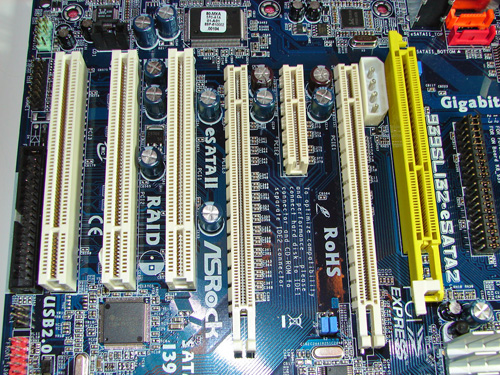
The first physical PCI Express x16 connector is located next to the 12V power connector that must be used if two video cards are installed. The PCI Express x4 and second PCI Express x16 connectors are located next and followed by the (3) PCI slots.
We did not have any issues installing our EVGA 7800GTX 512MB or ATI X1900XTX video cards in the first and second x16 PCI Express slots. These dual slot configuration cards will physically render the PCI Express x4 and first 32-bit PCI slot useless. We did not have any issues utilizing these slots with video cards containing single slot cooling systems.
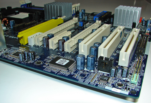
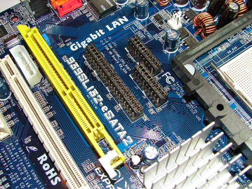
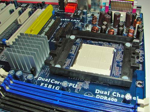
The ULI M1695 chipset is passively cooled with a large heat sink unit that did not interfere with any installed peripherals. However, this unit did not keep the M1695 chipset cooled properly. We typically witnessed temperatures hovering near 59c from this heat sink, although we did not notice any stability issues during load operations. We do believe additional cooling in this area is required.


46 Comments
View All Comments
Zoomer - Tuesday, March 7, 2006 - link
I believe it should be included to comparison's sake. And perhaps push manufacturers to adopt it.If new HD camcorders supports firewire 800, the market will be there right away. Too bad they aren't backward compatible.
deathwalker - Thursday, March 2, 2006 - link
At $85 I don't see how anyone could ask for much more in a motherboard...SLI/eSATA//8 channel sound/varity of Raid array choices. Can't hardly beat this for a basic and even higher platform. Kadoos to Asrock for a worthy effort. Before this thread is over someone will be slamming this mobo from some position other than one of using a rational approach for what you would be getting for $85 and they will be trying to compare it to a competetors $150 motherboard. AT..keep up the good work.Pete84 - Thursday, March 2, 2006 - link
The Asrock AM2 riser has been spied.http://www.hkepc.com/bbs/blog.php?tid=558875&s...">http://www.hkepc.com/bbs/blog.php?tid=5...time=114...
poohbear - Thursday, March 2, 2006 - link
Just remember ASRock is a dodgy mobo company. In their Dualsata2 mobo they gave reviewers a bios that allowed em to overclock using the 300mhz cpu frequency then they cap it @ 274 in subsequent bios'. Meanwhile, us customers read the reviews and their site/manual which states it can support a 300cpu frequency only to find a a 274mhz cap. Very deceptive of em. The dual sata2 was the only mobo that provided native agp and pci-e, so ASRock got away w/ dodgy BS like that cause there was no other company offering the Uli1695 chipset.In this situation, there are a ton of other exceptional PCI-E mobos, especially w/ ATI's 580 just being released, so why even consider em?!
sandorski - Thursday, March 2, 2006 - link
that's not what happened. go back and re-read what that was about.Gary Key - Thursday, March 2, 2006 - link
I would not consider ASRock a dodgy motherboard company. We at times find the initial bios releases to contain performance enhancements or features that might not be available upon production release of the boards. We (along with others) provide feedback to the manufacturers about the stability, features, or performance during testing. At times this feedback will cause the manufacturer to change the bios features to improve stability or as in our Biostar NF4 article to improve performance also.
We are taking a more serious stance with the motherboard companies in regards to their bios features before publishing an article. We could have published this article with the .17 bios release (not available) and shown additional voltage features along with improved performance as mentioned in the article. We waited until ASRock had the production release bios available before publishing our revised test results. We found the board to be better behaved with the release bios at the expense of performance. However, this the correct path as being able to score a few additional points in a benchmark or overclocking that extra bit is not important if the board produces BSOD results on a consistent basis. It also is not wise to release a bios with features the public will never see. I personally still have issues with Asus and the 0047 bios we tested on the P5N32-SLI board. Some of the features of that bios are still not available at this time and it is worrisome to publish an opinion about a board and not see the same level of performance or stability in the released product.
While there are other alternatives (excellent ones at that) I doubt you will find a board with this combination of performance and features for $85. If you are hard core overclocker this is not the board for you. If you like to casually overclock without pushing the boundaries then this board will suffice for a great number of people. It is all about choices and fortunately we will see some additional M1697 based boards before NVIDIA completes their assimilation of ULi. ;-)
poohbear - Thursday, March 2, 2006 - link
that's definetly good to hear. it's blatantly unacceptable when mobo manufacturers want to promote something that is'nt in their mobo so they can get good initial reviews and hence sell more, and then disable said feature when it becomes inconvenient to support. (the Dualsata2 still proports to support 300 cpu frequency both on ASRock's site and in their online manual, but it's simply not supported)
nemesismk2 - Friday, March 3, 2006 - link
You have said a couple of times that on the Asrock website it states that the Asrock 939 Dual Sata2 supports 300 Mhz CPU Frequency, can you tell me where because I can't find anywhere on http://www.asrock.com/product/939Dual-SATA2.htm">http://www.asrock.com/product/939Dual-SATA2.htm which confirms what you have been saying?nemesismk2 - Thursday, March 2, 2006 - link
Asrock are NOT a dodgy company at all, they are just a company who supply good quality budget motherboards which are not designed for overclocking. Yes it was found that the motherboard could use 300mhz cpu frequency with an early bios but it was also found that the motherboard wasn't stable using that frequency so it was reduced for stability reasons. I've never had any stability problems with my Asrock 939 Dual Sata2 so their decision was correct for most users, good work Asrock! :)poohbear - Thursday, March 2, 2006 - link
ppl w/ beta bios were running this mobo 350+ cpu frequency, so how can u say it's not stable? they're just not fixing it because, yes, they could care less about anybody who overclocks, but they shouldnt give the impression that this mobo supports something it doesnt. For all we know anandtechs overclock w/ this mobo might be completely misleading because ASRock might do the same thing and disable any such features when it's inconvenient for them to support em.