P55 Extreme Overclockers: Check your sockets!
by Rajinder Gill on October 15, 2009 12:01 AM EST- Posted in
- Motherboards
We start with a picture.
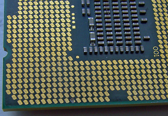
The picture above is after our Core i7 870 (LGA-1156) processor was overclocked up to 5.19GHz using our cascade with a -102° Celsius evaporator head temperature under full-load. Processor VCC power draw at these frequencies is around 160W (this is possible only due to subzero cooling), as measured with a clamp meter installed at the 12V EPS power lead. Study the pictures closely and you should notice something peculiar. Keep in mind it comes from a CPU installed in the same type of socket from a particular manufacturer.
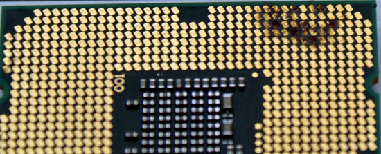
What happens after several extreme benchmark runs...
If you noticed something weird in the pictures then you understand the title of our article. We have what seems to be a potentially serious issue with proper socket loading on several P55-based motherboards when overclocking to the limit. We are of course not the only ones experiencing the problem as several of our overclocking peers have run into the same problem.
Normally we do not worry too much about mishaps during extreme overclocking testing as they are typically caused by factors outside of the supplier’s control. The overriding concern is that we have damaged every motherboard in our possession for the P55 overclocking (extreme) shootout as well as two very expensive i7/870 processors. These problems are the cause of a single component and are repeatable. As such, we thought we would provide details on current problems and will provide an update once all of the motherboard manufacturers affected have had a chance to properly respond.
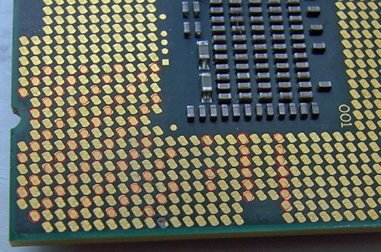
We draw your attention to the fact that the processor shown in this pictures exhibits signs of insufficient pin-to-pad contact (little to no contact) in what is a rather reproducible pattern with Foxconn manufactured 1156 sockets. As soon as an end-user mounts a CPU in a socket and latches the clamp mechanism, each pin should leave a notable mark on the associated pad.
We've marked locations where this does not seem to have happened, showing what appears to be a significant reduction in the number of VCC/VSS pins for proper power delivery, and certainly not at the right load line resistance. Damage resulting from highly overclocked use in these types of situations is not solely limited to the processor; let’s take a look at what happened to some of the motherboards in which these CPU were seated.
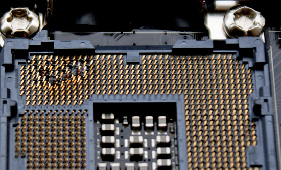
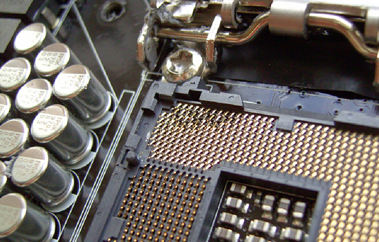
When Intel publishes socket specifications and design tolerances, it's up to component manufacturers to strictly adhere to them when designing, manufacturing, testing and ultimately selling their "compliant" components. Of course, that's not to say Intel could not have goofed when releasing their specification, leaving out a crucial tolerance or such. It could happen, but not likely. For the time being, let's assume that's not the case; seeing as how processors installed in sockets built by other companies have exhibited no such issue in testing to date.
At first glance, one might be inclined to think LGA-1156 based processors are intolerant of high-end overclocking, almost as if by design. This is correct to some extent; a quick glance at Intel’s white papers for socket 1156 CPU’s reveals that there are around 175 pads for VCC compared to over 250 for socket 1366 CPU’s. This means socket 1156 has around 66% of the current capacity of socket 1366, the caveat being that when overclocked, processors from both platforms draw similar levels of current.
When overclocked above 4GHz, processors from both platforms will draw around 15-16 amps via the EPS 12V rail to VCC, VTT and some of the other sub –system power rails under full 8 thread load from the Intel burn test (Linx). Assuming 85% PWM efficiency, we’re looking at power draw in the region of 130-140w to VCC on both platforms. The facts point toward tighter current handling tolerances for socket 1156 when compared to socket 1366, especially when it comes to non-connection of VCC/VSS power delivery pins.
Fortunately, we think we've been able to isolate pin to pad contact issues to one particular brand of parts. Physical inspection and end-user reports all but confirm the issues only affects sockets manufactured by Foxconn at this time. The only known alternative sockets in the wild are made by LOTES or Tyco AMP. We happen to have a couple of boards from EVGA using the LOTES/Tyco AMP sockets and MSI/DFI using the LOTES socket design, and thus far those boards have been issue free given highly similar operating conditions. In fact, we’ve managed to push our LGA-1156 processors further in heavy load tests on boards made using LOTES/Tyco AMP sockets than those made with sockets from Foxconn; something we’re not putting down solely to coincidence.
So far, EVGA is the only company we know that uses sockets exclusively from LOTES on their top-tier P55 boards - for example, the EVGA P55 Classified 200, model E659. This by the way may be the onus behind the decision to market the board’s “300% More Gold Content” socket statement as a purchasing option point. If you find yourself shopping for an EVGA P55 FTW, model E657, you've got a 50/50 chance of buying one with a Tyco AMP socket design (using a LOTES backplate), as opposed to one made solely with Foxconn's, the same goes for MSI and DFI who have batches of boards in the retail channel using LOTES sockets (although we're not entirely sure on socket specifics at this point). DFI told us earlier they have dropped usage of the Foxconn sockets completely until further notice. We hear the LOTES and Tyco AMP sockets are in short supply, which is probably why Foxconn's been able to fill the void in the market with what we believe to be a lower quality alternative for the extreme overclocker.
We took one of our damaged CPU’s and inserted it into one of the EVGA (LOTES/Tyco AMP) boards and took a few pics to show contact scoring and a side by side compare to the original Foxconn socket indents.
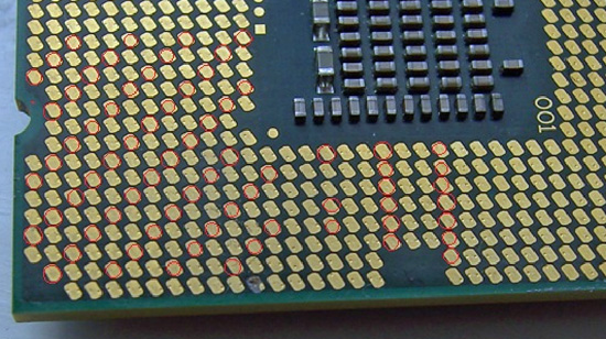
Foxconn 1156 Socket Installation
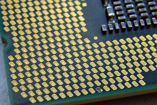
Tyco AMP / LOTES 1156 Socket Installation
Note how from a variety of angles certain pads show no evidence of contact from a Foxconn pin at all. Both the Tyco AMP and LOTES sockets have a larger pin/pad contact surface area leaving a slight scuff mark in the central area of each pad. In light of this, what we will say is that if you’re thinking of doing extreme overclocking on a board built using Foxconn's socket 1156, think again. Or, at least check your CPU for evidence of proper pin-to-pad contact.
We have not had any problems with air or water cooling overclocking up to 4.3GHz, although we do have a i5/750 that has developed a few dark pads after a thousand hours or so of constant overclocking. However, none of the boards have developed pin problems so we feel very safe in saying that any problems will probably occur only in extreme overclocking scenarios.
We also realize that partial responsibility for some of the less than acceptable CPU installations may be in fact due user installation errors. However, if users are screwing this up by doing nothing different than what they've always done when it comes to handling and installing LGA-type processors, then it's hard for us to find fault with the installer. Be aware of this situation and study the pin imprint on the CPU pads and make sure you have good contact on the VCC/VSS power delivery pads before pushing the system too hard.


273 Comments
View All Comments
chrnochime - Friday, October 16, 2009 - link
The boards aren't QA'd in Taiwan, they're QA'd where they're manu.Don't group Taiwanese products with Foxconn. There are products that excel in their respective areas, this isn't one of them.
If you don't know WTF you're talking about, it'd be wise to stay silent.
Rindis - Thursday, October 15, 2009 - link
Who saw the (presumably) bum pad on the bottom row in the first photo and assumed that's what the problem was going to be?Sandmen - Thursday, October 15, 2009 - link
An electronic technician with 50 years experience.How do you think those marks come to be there after some insane OC?
DahakaCL - Thursday, October 15, 2009 - link
Hi there, sorry for my english :uy.Few days ago i buy a Maximus III Formula and recently i red this great article, if anybody have some references or detail about this MB from asus will be just great.
In two weaks more y was planing a OC session with Dry Ice and F1 pot from Kingpin.
Regards from Chile.
Rajinder Gill - Thursday, October 15, 2009 - link
Make sure pin to pad contact is good if you can before you start out. Assuming the CPU is brand new, you should get a good indication of how many pins are making contact with pads.So far, we've had two Maximus III boards with the problem under 'extreme OC' (if you can call it that).
later
Raja
Sandmen - Thursday, October 15, 2009 - link
Lack of indentations could present a problem but will not ruin your CPU and/or MB and you will have the rigth to a replacement.On the other hand, the second picture on this review clearly shows several overheated points of contacs on the sockets (and you can be sure that the matching pins in the CPU had been damaged too)and in this case the manufactures (Intel or MB's ones) will have the rigth to refuse replacing this units.
People needs to understand the difference between keeping the core from melting (thru good cooling) and the capacity of the pins contacts to handle the very large amounts of current needed for this extreme overclocking.
This pins and sockets are not designed to widstand heavy OC because plain and simply there is no room to make them any larger.
Personally, I OC'd my i7-860 from 2.80 MHz to 3.5 MHz. That is a 25% increase end everybody should be happy with this kind of improvement.
muddocktor - Thursday, October 15, 2009 - link
No, IMHO you are missing the point here. The lack of indentations on some of the pads points to sloppy tolerances in the socket design or execution and are not acceptable in any case. Since this socket is so new, who knows what kind of life you will get out of a crap built socket even running at stock speeds over the course of some years instead of a few months. Intel designed this socket to support a set number of pads and pins to deliver power efficiently and safely to the processor and if the pins in the socket aren't making proper contact then the socket manufacturer isn't following Intel's design guidelines for the socket, since it is forcing fewer pads and pins to deliver more current due to lack on contact on the "bad" pins in the socket.SixOfSeven - Thursday, October 15, 2009 - link
"...who knows what kind of life you will get out of a crap built socket even running at stock speeds over the course of some years instead of a few months."Exactly.
IKeelU - Thursday, October 15, 2009 - link
I will preface this by saying that overall I believe this article to be good thing since it informs serious overclockers of an unsuitable product for their hobby.That being said, laying the blame at the hardware manufacturer(s) doorstep (either Foxconn for not adhering to the spec, or Intel for "goofing" up in designing the spec) is absolutely absurd. You guys significantly overclocked your processors; ie. you ran them *completely* out of specifications. At which point something broke, and you then point your fingers at the hardware manufacturers. The only parties who we actually know (for a fact) were out of spec are those who overclocked their CPUs.
If you want to accuse Foxconn of anything, look up Intel's specs and do some real materials testing on their product. "oooh look, we can't see the pin marks" - so very, very lame.
SixOfSeven - Thursday, October 15, 2009 - link
Uh, read my post again. My CPU pads look like the ones pictured here; I ran at stock settings; I saw flaky behavior consistent with poor power delivery to the CPU. I seriously doubt that I'm the only one.In any case, it's a little sleazy for MB manufacturers to promote boards based on their overclocking prowess and then refuse to support them because users overclocked the things.