ASRock 939SLI32-eSATA2: ULi Dual x16 SLI
by Gary Key on March 2, 2006 12:15 PM EST- Posted in
- Motherboards
ASRock 939SLI32-eSATA2: Features
ASRock designed a very well laid out board with all major connections easily reached. The Asrock layout provides excellent clearance for cards and components and it was easy to install in a mid-size ATX case. Although the board features a 3-phase voltage regulator power design, it provided excellent stability and allowed for a decent level of overclocking.
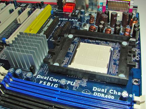
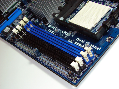
The DIMM module slots' color coordination is correct for dual channel setup. The memory modules are easy to install with a full size video card placed in the first PCI Express x16 slot.
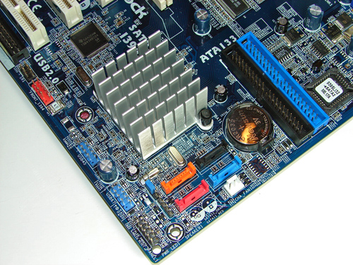
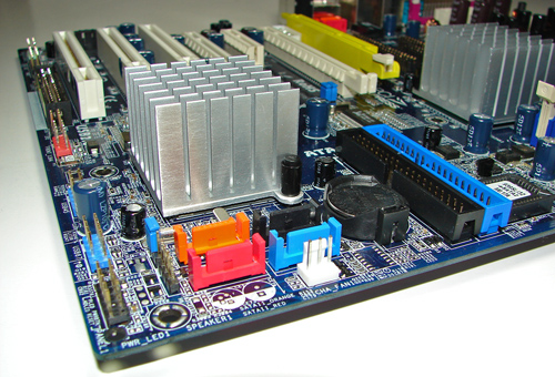
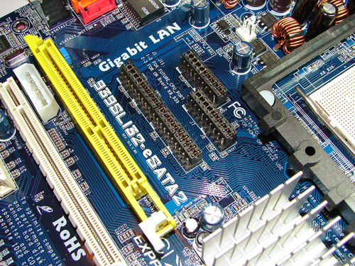
The ULi IDE port connectors are located to the right of the battery and left of the BIOS chip. The IDE port connectors presented connection issues when utilizing the board in SLI operation. The ability to connect our IDE cables with the SLI setup was severely hampered due to the tight space in between the two 7800GTX video cards. The cables were forced to run vertically in between the video cards and then loop over the first video card. This could present an issue for owners having a full size ATX case with optical drives at the top of the case. We also noticed temperature readings of around 56c in between the video cards where the two cables were installed.
The system fan header is located below the ULi SATA ports. The ULi SATA ports are conveniently located below the M1697 chipset and to the left of the battery. The SATA ports feature the new "clamp and latch" design along with it being color-coded. The ULi M1697 chipset is passively cooled with a high rise heat sink that did not interfere with cards installed into the PCI slots. The TI TSB43AB22 IEEE 1394 chipset is located above the M1697 chipset.
The ULi USB connectors, chassis panel, and IEEE 1394 header are located on the left edge of the board. The clear CMOS jumper block is a traditional jumper design located to the left of the orange SATA port connector. The orange and red ULi SATA port connectors are color-coded to match the eSATA2 ports on the I/O panel. ASRock supplies cables to attach the two ports to their matching ports on the I/O panel in order to utilize the external ports.
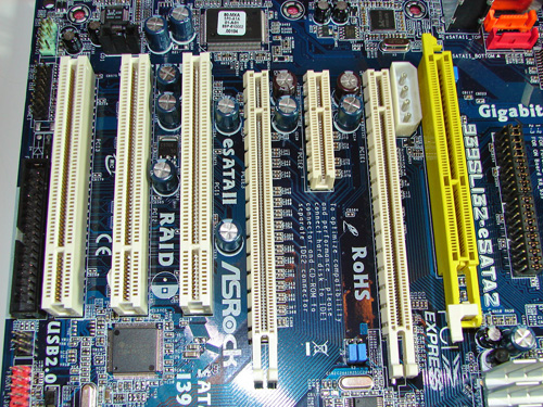
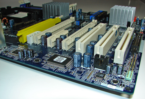
The board comes with (2) physical PCI Express x16 connectors, (1) PCI Express x4 connector, and (3) 32-bit PCI 2.2 connectors. The layout of this design offers a very good balance of expansion slots for a mainstream board.
The first physical PCI Express x16 connector is located next to the 12V power connector that must be used if two video cards are installed. The PCI Express x4 and second PCI Express x16 connectors are located next and followed by the (3) PCI slots.
We did not have any issues installing our EVGA 7800GTX 512MB or ATI X1900XTX video cards in the first and second x16 PCI Express slots. These dual slot configuration cards will physically render the PCI Express x4 and first 32-bit PCI slot useless. We did not have any issues utilizing these slots with video cards containing single slot cooling systems.
The floppy drive connector is located to right of the number three PCI slot and is inconveniently located for most case designs. The game port header and front audio panel header are located in front of the floppy drive connector and to the right of the number three PCI slot. The internal CD audio connector is located in front of the number two and three PCI slots along with the Realtek ALC660 audio codec. The Winbond Super I/O chipset is located in front of the number one PCI slot.
The board features a dedicated CPU upgrade slot that will fully support the 940-pin AM2 series of CPUs with the proper daughter card. This daughter card option should be available from ASRock shortly after the launch of the AM2 CPUs. The jumpers to the right of the yellow are required to be changed in order to switch from 939 socket operation to the AM2 CPU.
Returning to the CPU socket area, we find ample room for alternative cooling solutions. We utilized the stock AMD heat sink, but also verified that several aftermarket cooling systems such as the Thermaltake Big Typhoon would fit in this area during our overclocking tests. However, due to the large heat sink covering the M1695 chipset, the installation of larger air or water-cooling solutions could be problematic.
The ULI M1695 chipset is passively cooled with a large heat sink unit that did not interfere with any installed peripherals. However, this unit did not keep the M1695 chipset cooled properly. We typically witnessed temperatures hovering near 59c from this heat sink, although we did not notice any stability issues during load operations. We do believe additional cooling in this area is required.
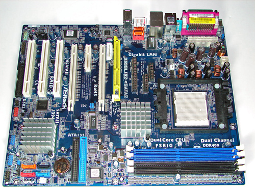
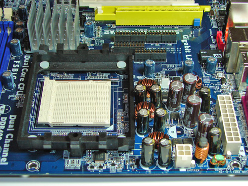
ASRock places the four-pin 12v auxiliary power connector at the top of the CPU socket area along the edge of the board, but out of the way of most aftermarket cooling solutions. The 20-pin ATX power connector is located above the capacitors and behind the rear I/O panel. This 20-pin connector is located in an unusual position and could hamper airflow with cabling that crosses directly over the CPU heat sink/fan; although, we did not have any issues in our case.
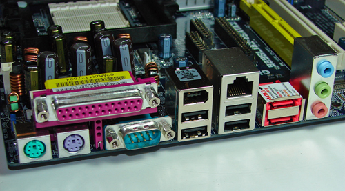
The rear panel contains the standard PS/2 mouse and keyboard ports, parallel port, serial port, LAN port, and 4 USB ports. The audio panel consists of 3 ports that can be configured for 2, 4, and 5.1 channel audio connections. Located to the right of the serial and parallel ports are the first two USB 2.0 ports with the IEEE 1394 connector on top. Located next to this series of ports are the next two USB 2.0 ports with the RJ-45 LAN port on top. The eSATA2 ports are located to the right of the USB/LAN ports and to the left of the audio panel.
ASRock designed a very well laid out board with all major connections easily reached. The Asrock layout provides excellent clearance for cards and components and it was easy to install in a mid-size ATX case. Although the board features a 3-phase voltage regulator power design, it provided excellent stability and allowed for a decent level of overclocking.
The DIMM module slots' color coordination is correct for dual channel setup. The memory modules are easy to install with a full size video card placed in the first PCI Express x16 slot.
The ULi IDE port connectors are located to the right of the battery and left of the BIOS chip. The IDE port connectors presented connection issues when utilizing the board in SLI operation. The ability to connect our IDE cables with the SLI setup was severely hampered due to the tight space in between the two 7800GTX video cards. The cables were forced to run vertically in between the video cards and then loop over the first video card. This could present an issue for owners having a full size ATX case with optical drives at the top of the case. We also noticed temperature readings of around 56c in between the video cards where the two cables were installed.
The system fan header is located below the ULi SATA ports. The ULi SATA ports are conveniently located below the M1697 chipset and to the left of the battery. The SATA ports feature the new "clamp and latch" design along with it being color-coded. The ULi M1697 chipset is passively cooled with a high rise heat sink that did not interfere with cards installed into the PCI slots. The TI TSB43AB22 IEEE 1394 chipset is located above the M1697 chipset.
The ULi USB connectors, chassis panel, and IEEE 1394 header are located on the left edge of the board. The clear CMOS jumper block is a traditional jumper design located to the left of the orange SATA port connector. The orange and red ULi SATA port connectors are color-coded to match the eSATA2 ports on the I/O panel. ASRock supplies cables to attach the two ports to their matching ports on the I/O panel in order to utilize the external ports.
The board comes with (2) physical PCI Express x16 connectors, (1) PCI Express x4 connector, and (3) 32-bit PCI 2.2 connectors. The layout of this design offers a very good balance of expansion slots for a mainstream board.
The first physical PCI Express x16 connector is located next to the 12V power connector that must be used if two video cards are installed. The PCI Express x4 and second PCI Express x16 connectors are located next and followed by the (3) PCI slots.
We did not have any issues installing our EVGA 7800GTX 512MB or ATI X1900XTX video cards in the first and second x16 PCI Express slots. These dual slot configuration cards will physically render the PCI Express x4 and first 32-bit PCI slot useless. We did not have any issues utilizing these slots with video cards containing single slot cooling systems.
The floppy drive connector is located to right of the number three PCI slot and is inconveniently located for most case designs. The game port header and front audio panel header are located in front of the floppy drive connector and to the right of the number three PCI slot. The internal CD audio connector is located in front of the number two and three PCI slots along with the Realtek ALC660 audio codec. The Winbond Super I/O chipset is located in front of the number one PCI slot.
The board features a dedicated CPU upgrade slot that will fully support the 940-pin AM2 series of CPUs with the proper daughter card. This daughter card option should be available from ASRock shortly after the launch of the AM2 CPUs. The jumpers to the right of the yellow are required to be changed in order to switch from 939 socket operation to the AM2 CPU.
Returning to the CPU socket area, we find ample room for alternative cooling solutions. We utilized the stock AMD heat sink, but also verified that several aftermarket cooling systems such as the Thermaltake Big Typhoon would fit in this area during our overclocking tests. However, due to the large heat sink covering the M1695 chipset, the installation of larger air or water-cooling solutions could be problematic.
The ULI M1695 chipset is passively cooled with a large heat sink unit that did not interfere with any installed peripherals. However, this unit did not keep the M1695 chipset cooled properly. We typically witnessed temperatures hovering near 59c from this heat sink, although we did not notice any stability issues during load operations. We do believe additional cooling in this area is required.
ASRock places the four-pin 12v auxiliary power connector at the top of the CPU socket area along the edge of the board, but out of the way of most aftermarket cooling solutions. The 20-pin ATX power connector is located above the capacitors and behind the rear I/O panel. This 20-pin connector is located in an unusual position and could hamper airflow with cabling that crosses directly over the CPU heat sink/fan; although, we did not have any issues in our case.
The rear panel contains the standard PS/2 mouse and keyboard ports, parallel port, serial port, LAN port, and 4 USB ports. The audio panel consists of 3 ports that can be configured for 2, 4, and 5.1 channel audio connections. Located to the right of the serial and parallel ports are the first two USB 2.0 ports with the IEEE 1394 connector on top. Located next to this series of ports are the next two USB 2.0 ports with the RJ-45 LAN port on top. The eSATA2 ports are located to the right of the USB/LAN ports and to the left of the audio panel.
46 Comments
View All Comments
chesss - Tuesday, March 7, 2006 - link
hmm I was hoping for a more definite answer from anandtech about this. Anybody else?Gary Key - Tuesday, March 7, 2006 - link
What type of information are you looking for at this time? We have seen prototype AM2 daughter cards but have not been able to test a card yet due to ongoing engineering changes. Although the daughter card will have direct HT access through the M1695 chipset, we have to wonder how well ASRock will be able to optimize the DDR2 memory performance. The daughter card will also limit cooling options available for the CPU choice. The other variable will be cost and if you are upgrading to AM2 then the additional cost of a motherboard in this category should not be an issue. When all is said and done we still think this is a marketing driven feature and not a viable engineering solution for most users.itroxx - Wednesday, March 8, 2006 - link
Hello everybody,I'am also looking for a new system for mainly video editing. Working with Premiere, MPEG2 encoding and DVD authoring. Thats why I found this review cause the AsRock seems the only board available with SATA2-Raid capabilities right now. But I am not sure about how much SATA2 drives can be attached. Is it possible to attach one SATA2 drive for the system and build a Raid0 of two more SATA2 drives? For what reason are the SATA connector on the rear panel?
The components I've selected at this point are
AMD Athlon64 X2 3800+ 2x2000MHz 2x512kB Box E4-Stepping
Asrock 939SLI32-eSATA2 S939 ATX
2x 1024 Corsair DDR400
1x Samsung 80GB SATA2 (System)
2x Samsung 250GB SATA2 (Raid0)
256MB PCIe x16 ATI RADEON X1300 PRO
What do you think of my selection? What type of power suply do I need?
Is 400 Watt enough?
thanks a lot and greetings from germany
Daniel
Redrider - Thursday, March 9, 2006 - link
Although my expertise is much lower than most of the people on this forum, there are a few things I have gleaned from my experience and research. Here are a couple of suggestion:You want the best you can get for the money you spend so as for the processor (I am seriously considering an X2 3800+ myself) I would go for the http://www.amdcompare.com/us-en/desktop/details.as...">ADA3800DAA5CD
which has the E6 stepping which is a newer revision based on http://www.techpowerup.com/articles/overclocking/2...">this article
Also, I would boost your power supply. You are spending some serious cash and I don't think skimping on the PS is wise. 400W seems pretty small and I would go with big power overhead just to be sure.
UJMA - Saturday, March 4, 2006 - link
The people who invariably buy SLi enabled boards are gamers, and gamers love to OVERCLOCK! unfortunately Asrock have provided this board with a feeble set of voltage options, both the Vdimm & Vcore voltage options are pathetic. No problem, if you're handy with a soldering iron as I'm pretty sure some voltage mods will eventually show up for entusiasts. Probably a better option would be to wait for Epox to launch their new EP-9U1697 GLI mobo based on the same ULi M1697 chipset, you'll get SLi with better overclocking options for a similar outlay!Gary Key - Saturday, March 4, 2006 - link
We just happen to have that board available for testing now. :)
UJMA - Friday, March 24, 2006 - link
2 great reviews on boards using the ULi M1697 chipset. In the red corner we have the Asrock 939SLI32-eSATA2, in the blue corner we have the EPoX EP-9U1697-GLi ... I'm going for the Epox board.Wesley Fink - Saturday, March 4, 2006 - link
Keep in mind the Epox is dual x8 using a single M1697 chipset, while the ASROCK is an amazing dual x16. If dual x8 is enough for you though, the Epox should be an interesting board.UJMA - Saturday, March 4, 2006 - link
I was looking at the Epopx website specs ..."Two PCI Express (x16) connector compliant with PCI Express 1.0a"
http://www.epox.com.tw/eng/products_content.php?ps...">http://www.epox.com.tw/eng/products_content.php?ps...
Gary Key - Saturday, March 4, 2006 - link
There are two physical x16 connectors on the Epox board but they are electrically x8 lanes in SLI mode. The ASRock 939SLI32 has the same physical x16 connectors but electrically they are x16 lanes in SLI mode.