ASRock 939SLI32-eSATA2: ULi Dual x16 SLI
by Gary Key on March 2, 2006 12:15 PM EST- Posted in
- Motherboards
Basic Features: ASRock 939SLI-32 eSATA2
The ASRock 939SLI32-eSATA2 is a member of the Socket 939 Series product family and is a value-based board targeted towards the enthusiast user. The board ships with an accessory package that includes the standard assortment of IDE/SATA cables and power connectors. ASRock also includes an extensive driver CD along with desktop utilities.
| Specification | ASRock 939SLI32-eSATA2 |
| CPU Interface | 939-Pin Socket supporting AMD Athlon 64 / 64FX / 64X2 |
| Chipset | ULi M1695 - North Bridge ULi M1697 - South Bridge |
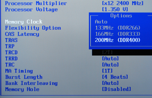
| Bus Speeds | 150MHz ~ 400MHz in 1MHz increments |
| CPU Clock Multiplier | Auto, 4x ~ 25x in 1x increments |
| Memory Speeds | Auto, 133MHz, 166MHz, 200MHz |
| PCI Bus Speeds | Auto, Sync with PCI-E, 33.33MHz ~ 37.50MHz variable speed |
| PCI Express Bus Speeds | Auto, 75MHz ~ 200MHz in various increments |
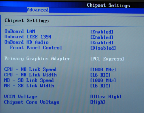
| HT Multipliers | Auto, 200MHz, 400MHZ, 600MHz, 800MHz, 1000MHz |
| HT Link Speed | Auto, 8-bit, 16-bit |
| Core Voltage | Auto, 0.800V to 1.400V (in 0.025V increments), (max voltage dependent upon CPU) |
| DRAM Voltage | Auto, 2.55V, 2.6V, 2.7V, 2.8V (Low, Normal, High, Ultra) |
| Chipset Voltage | Auto, 2.10V, 2.20V (Normal, High) |
| Memory Slots | (4) x DIMM, max. 4GB, DDR 400/333/266, non-ECC, un-buffered memory, Dual Channel Operation supported. |
| Expansion Slots | (2) x PCI-E x16 (each slot operates in 1x16 mode) (1) x PCI-E x4 (operates in x1 or x2 mode) (3) x PCI 2.2 (1) x AM2 CPU port |
| Onboard SATA | ULi M1697: (4) x SATA II , (2) eSATA II (shared with SATA II) |
| Onboard IDE | ULi M1697: (2) x UltraDMA 133/100/66/33 |
| SATA/IDE RAID | ULi M1697: (4) x SATA II RAID 0, RAID 1, RAID 0+1, RAID 5, JBOD |
| Onboard USB 2.0 | (8) USB2.0 ports (four ports, two headers for four more ports) |
| Onboard LAN | Realtek RTL8111B PCI-E 10/100/1000Mb/s LAN - PHY |
| Onboard Audio | Realtek ALC-660, 5.1 channel capable HD Audio Codec |
| Onboard Firewire | TI TSB43AB22 IEEE 1394 chipset - 1394A capable |
| Power Connectors | 20-pin ATX 4-pin ATX 12V 4-pin 12V SLI |
| Back Panel I/O Ports | 1 x PS/2 Keyboard 1 x PS/2 Mouse 1 x Parallel (ECP/EPP) 1 x Serial (COM1) 1 x Audio I/O Panel 1 x RJ45 LAN 4 x USB 2.0 2 x eSATA II 1x IEEE 1394 |
| Other Features | Hybird Booster - Overclocking Engine Boot Failure Guard - Overclocking Safe Guard United Overclocking Program - Fixed PCI-E and PCI speeds Hardware Monitor - BIOS Based Windows Vista Ready ROHS Compliant |
| BIOS | AMI 1.0 (2/06/06) |
The ASRock 939SLI32-eSATA2 is a member of the Socket 939 Series product family and is a value-based board targeted towards the enthusiast user. The board ships with an accessory package that includes the standard assortment of IDE/SATA cables and power connectors. ASRock also includes an extensive driver CD along with desktop utilities.


46 Comments
View All Comments
Gary Key - Saturday, March 4, 2006 - link
It works very well on this board with an Opteron. ;-)Kiste - Thursday, March 2, 2006 - link
In the past, Realtek has solved performance issues by reducing the number of buffers and disabling EAX effects without telling anyone. I hope someone will have a really good look at these integrated audio solutions one day, one that isn't just FPS and CPU utilization.
Gary Key - Thursday, March 2, 2006 - link
To date with the HD Codecs, Realtek has not decreased the buffers nor have we noticed changes in EAX2 output except for the positive. It is a very subjective area to comment on but in BF2 I like the sound quality of the 1.29 drivers better but Serious Sam II seems to have improved a great deal in the 1.30 and 1.31 drivers. While the on-board audio solutions are still lacking in most areas compared to the add-in solutions at least the manufacturers (board/chipset) are trying to improve quality in this area instead of pumping out the same old AC97 codecs. If it were not for the cost I think we would have seen several additional Audigy-SE solutions on the motherboards by now and even possibly an improved offering from Creative. While the A-SE is an older chipset it does offer better performance and audio quality in gaming than the current HD codecs from Realtek, C-Media, ADI, and SigmaTel. I really thought the VIA Envy24 series would have had greater market penetration on the motherboards but one can only speculate as to why this never happened. ;->
tjpark1111 - Thursday, March 2, 2006 - link
is it just me, or does this thing have a 20-pin power connector. ?!?!?!??!???kelim - Thursday, March 2, 2006 - link
Yes, the board does in fact use a 20-pin power connection. If you have a 24-pin PSU, this shouldn't be a problem, since most are 20+4-pin, meaning you can detach the extra 4 pins and only use the ones you need. Either that, or the uneeded pins will hang off the side.Gary Key - Thursday, March 2, 2006 - link
You are correct, it is a 20-pin ATC connector as stated in the article. I was surprised also and did a double take after removing it from the box. :)dab - Thursday, March 2, 2006 - link
It says that this motherboard supports ddr2,"(4) x DIMM, max. 4GB, DDR2 400/333/266, non-ECC, un-buffered memory..."
Is this a joke? There's no 240pin slots on that board, only on the riser (which is not included). s939's IMC doesn't support this either..
Am I mistaken?
Gary Key - Thursday, March 2, 2006 - link
I was just changing that to DDR, sorry about the mistake. The AM2 daughter card will have slots for DDR2 memory.
Puddleglum - Thursday, March 2, 2006 - link
The figure is noteworthy, but it's actually the only Firewire 800 test result I can find in AT's reviews.Gary Key - Thursday, March 2, 2006 - link
I know we only have it in a recent review and probably should drop it. I keep hoping Firewire 800 will be implemented on the higher end boards or those designed for HTPC life. :) However, it appears to be a dead-end option at this point and the technology itself seems to be going away without a fight.